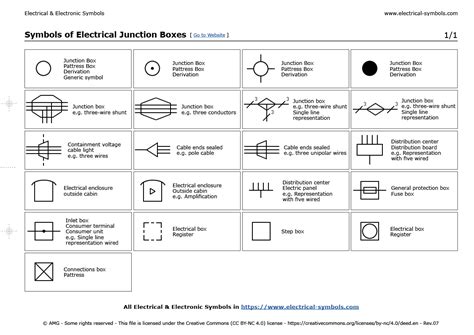
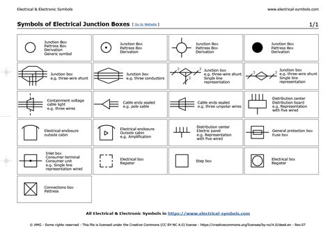
architectural symbol for electrical boxes Most of the electrical schematic symbols for data, phone, TV and sound used on blueprints have become standard. Some architects or designers may use slightly different symbols. Always check with the key on your blueprints. An electrical junction box (also known as a "jbox") is an enclosure housing electrical connections. [1] Junction boxes protect the electrical connections from the weather, as well as protecting people from accidental electric shocks.
0 · underfloor bus junction box symbol
1 · pull box symbol
2 · pull box electrical symbol
3 · junction electrical symbol
4 · junction box symbol electrical drawings
5 · electrical splice symbol
6 · electrical panel box symbol
7 · distribution box electrical symbol
The metal fabrication process encompasses manufacturing techniques like bending and cutting, using an array of advanced equipment to produce complex metal shapes, components, and assemblies.
Most of the electrical schematic symbols for data, phone, TV and sound used on blueprints have become standard. Some architects or designers may use slightly different symbols. Always check with the key on your blueprints. Below are some of the most common electrical symbols used in architectural blueprints: Standard Outlets: Typically represented by a circle connected by two parallel lines to a wall. This universally recognized symbol .Electrical plan symbols play a vital role in the planning, installation, and maintenance of electrical systems. By ensuring proper understanding and interpretation of these symbols, architects, .A concise glossary of residential electrical blueprint symbols. Also see our free tutorial - How to Read Blueprints.
The types of plan symbols you’ll find on floor plans include everything from doors and stairs to appliances, furniture, and electrical symbols. Here are the six most common types of symbols you will find on floor plans .North American symbol for electrical equipment shown on construction drawings. Some older sym-bols are either becoming obsolete over time or have been superseded by newer symbols .
Here are some of the most common electrical symbols used in architectural diagrams: Typically represented by a circle connected by two parallel lines on the wall, this universally recognized symbol denotes a typical outlet or . These plans utilize a comprehensive set of symbols that represent electrical components, allowing architects, engineers, and contractors to visualize the layout, .

electrical box through stucco
Electrical plan symbols used in electrical drawings, including power, lighting, security, fire alarm, and communications symbols.Most of the electrical schematic symbols for data, phone, TV and sound used on blueprints have become standard. Some architects or designers may use slightly different symbols. Always check with the key on your blueprints. The basic symbol for most lights is a circle and, as with duplexes, variations on how it is drawn and abbreviations next to it convey additional and essential information. The key on the floor plans will explain the particular symbols used on any project. Below are some of the most common electrical symbols used in architectural blueprints: Standard Outlets: Typically represented by a circle connected by two parallel lines to a wall. This universally recognized symbol indicates a typical outlet or receptacle with two sockets.
Electrical plan symbols play a vital role in the planning, installation, and maintenance of electrical systems. By ensuring proper understanding and interpretation of these symbols, architects, engineers, and electricians can work together to design and implement safe, efficient, and reliable electrical installations.A concise glossary of residential electrical blueprint symbols. Also see our free tutorial - How to Read Blueprints. The types of plan symbols you’ll find on floor plans include everything from doors and stairs to appliances, furniture, and electrical symbols. Here are the six most common types of symbols you will find on floor plans (versus other types of plans).North American symbol for electrical equipment shown on construction drawings. Some older sym-bols are either becoming obsolete over time or have been superseded by newer symbols (which are shown in this publication). Some electrical symbols are not widely used on construction drawings, but usually on wiring schematics and other types of more .
Here are some of the most common electrical symbols used in architectural diagrams: Typically represented by a circle connected by two parallel lines on the wall, this universally recognized symbol denotes a typical outlet or receptacle with two plugs.
These plans utilize a comprehensive set of symbols that represent electrical components, allowing architects, engineers, and contractors to visualize the layout, connections, and functionality of the electrical system.
Electrical plan symbols used in electrical drawings, including power, lighting, security, fire alarm, and communications symbols.Most of the electrical schematic symbols for data, phone, TV and sound used on blueprints have become standard. Some architects or designers may use slightly different symbols. Always check with the key on your blueprints. The basic symbol for most lights is a circle and, as with duplexes, variations on how it is drawn and abbreviations next to it convey additional and essential information. The key on the floor plans will explain the particular symbols used on any project. Below are some of the most common electrical symbols used in architectural blueprints: Standard Outlets: Typically represented by a circle connected by two parallel lines to a wall. This universally recognized symbol indicates a typical outlet or receptacle with two sockets.
Electrical plan symbols play a vital role in the planning, installation, and maintenance of electrical systems. By ensuring proper understanding and interpretation of these symbols, architects, engineers, and electricians can work together to design and implement safe, efficient, and reliable electrical installations.
A concise glossary of residential electrical blueprint symbols. Also see our free tutorial - How to Read Blueprints. The types of plan symbols you’ll find on floor plans include everything from doors and stairs to appliances, furniture, and electrical symbols. Here are the six most common types of symbols you will find on floor plans (versus other types of plans).North American symbol for electrical equipment shown on construction drawings. Some older sym-bols are either becoming obsolete over time or have been superseded by newer symbols (which are shown in this publication). Some electrical symbols are not widely used on construction drawings, but usually on wiring schematics and other types of more .
Here are some of the most common electrical symbols used in architectural diagrams: Typically represented by a circle connected by two parallel lines on the wall, this universally recognized symbol denotes a typical outlet or receptacle with two plugs.
underfloor bus junction box symbol

What does a CNC router do? A CNC router is an automatic machine tool with a computer-controlled system. It’s used for milling, drilling, engraving, cutting, and, of course, routing. A CNC router primarily cuts wood but can be used for lighter materials, including foam, plastics, acrylic, glass, copper, brass, aluminum, PVC, and MDF.
architectural symbol for electrical boxes|pull box symbol