cylindricity in sheet metal parts Cylindricity is a 3-Dimensional tolerance that controls the overall form of a cylindrical feature to ensure that it is round enough and straight enough along its axis. Cylindricity is independent of any datum feature the tolerance . Includes limited edition Steelbook. Newcomers or those whose Yakuza experience started with Yakuza 0 will have familiar, exacting controls, top-notch SEGA localization, and a solid starting point for entering the Yakuza .
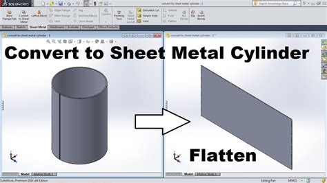
0 · solidworks sheet metal cylinder
1 · sheet metal parts with cylinders
2 · sheet metal parts with cylinder faces
3 · sheet metal cylinder face design
4 · how to measure cylindricity
5 · how to calculate cylindricity
6 · cylindricity vs circularity chart
7 · 3 dimensional cylindricity
1967 Mustang Coupe to Fastback Sheet Metal Structural Conversion Kit. This is a structural sheet metal kit to convert a Mustang coupe to the look of a Fastback. It includes the major exterior sheet metal pieces and inner structure components .
solidworks sheet metal cylinder
To create a sheet metal part with cylindrical faces: Sketch an open contour arc. The arc can also be tangent to a line. Single open contours can be used for extrudes, revolves, sections, paths, . Cylindricity is a 3-Dimensional tolerance that controls the overall form of a cylindrical feature to ensure that it is round enough and straight enough along its axis. Cylindricity is independent of any datum feature the tolerance . This section explains how to properly state tolerances for straightness, flatness, circularity, and cylindricity. These tolerances are used where size tolerances don’t provide .
General: Cylindricity is a GD&T callout that defines how closely the cylindrical surface of an actual part must match an ideal cylinder. It defines a tolerance zone bounded by two concentric .
Cylindricity . Similar to how circulatory is like straightness, cylindricity is much like flatness—only bent. Cylindricity combines controls for straightness and roundness, taking a 3D measurement .
What is GD & T ? When to use GD & T ? Why to use GD & T ? Leads to high productivity, less rework and reduced cost. Always need a Datum (Reference) Plane / Feature. If not specified, .Cylindricity tolerance in gd&t is a type of foam control tolerance, that defines the allowable deviation in a feature from actual true cylinders. It controls the circularity and surface .What is cylindricity tolerance in GD&T? Cylindricity tolerance in gd&t is a type of foam control tolerance that defines the allowable deviation in a feature from actual true cylinders. It controls .
As a form control, cylindricity focuses on the component’s shape. Cylindricity combines straightness and flatness, taking a 3-D measurement along the length of a part. The symbol for .
The cylindricity control is a GD&T tolerance from the form control group and guarantees a part’s cylindric shape by determining the two key aspects of roundness and axis straightness. Many cylindrical parts that fit into a tight assembly must be “cylindrical enough” for a .To create a sheet metal part with cylindrical faces: Sketch an open contour arc. The arc can also be tangent to a line. Single open contours can be used for extrudes, revolves, sections, paths, guides, and sheet metal. Typical open contours are sketeched with lines or other sketch entities.
Cylindricity is a 3-Dimensional tolerance that controls the overall form of a cylindrical feature to ensure that it is round enough and straight enough along its axis. Cylindricity is independent of any datum feature the tolerance needs to be less than the diameter dimensional tolerance of the part. Cylindricity essentially forms a perfect . This section explains how to properly state tolerances for straightness, flatness, circularity, and cylindricity. These tolerances are used where size tolerances don’t provide sufficient control of the part geometry. Form tolerances are not applicable to datums.General: Cylindricity is a GD&T callout that defines how closely the cylindrical surface of an actual part must match an ideal cylinder. It defines a tolerance zone bounded by two concentric cylinders. The surface of the inspected cylinder must lie within. Cylindricity combines in one callout circularity and straightness.Cylindricity . Similar to how circulatory is like straightness, cylindricity is much like flatness—only bent. Cylindricity combines controls for straightness and roundness, taking a 3D measurement along the entire length of the part. The cylindricity symbol is a .
What is GD & T ? When to use GD & T ? Why to use GD & T ? Leads to high productivity, less rework and reduced cost. Always need a Datum (Reference) Plane / Feature. If not specified, treat Feature Tolerance as RFS.Cylindricity tolerance in gd&t is a type of foam control tolerance, that defines the allowable deviation in a feature from actual true cylinders. It controls the circularity and surface straightness of a controlled feature in a part.

sheet metal parts with cylinders
What is cylindricity tolerance in GD&T? Cylindricity tolerance in gd&t is a type of foam control tolerance that defines the allowable deviation in a feature from actual true cylinders. It controls the circularity and surface straightness of a control feature of a part.As a form control, cylindricity focuses on the component’s shape. Cylindricity combines straightness and flatness, taking a 3-D measurement along the length of a part. The symbol for cylindricity. Tolerance Zones: How Far from the “Perfect” Cylinder? You can think of . The cylindricity control is a GD&T tolerance from the form control group and guarantees a part’s cylindric shape by determining the two key aspects of roundness and axis straightness. Many cylindrical parts that fit into a tight assembly must be “cylindrical enough” for a .To create a sheet metal part with cylindrical faces: Sketch an open contour arc. The arc can also be tangent to a line. Single open contours can be used for extrudes, revolves, sections, paths, guides, and sheet metal. Typical open contours are sketeched with lines or other sketch entities.
Cylindricity is a 3-Dimensional tolerance that controls the overall form of a cylindrical feature to ensure that it is round enough and straight enough along its axis. Cylindricity is independent of any datum feature the tolerance needs to be less than the diameter dimensional tolerance of the part. Cylindricity essentially forms a perfect .
This section explains how to properly state tolerances for straightness, flatness, circularity, and cylindricity. These tolerances are used where size tolerances don’t provide sufficient control of the part geometry. Form tolerances are not applicable to datums.General: Cylindricity is a GD&T callout that defines how closely the cylindrical surface of an actual part must match an ideal cylinder. It defines a tolerance zone bounded by two concentric cylinders. The surface of the inspected cylinder must lie within. Cylindricity combines in one callout circularity and straightness.Cylindricity . Similar to how circulatory is like straightness, cylindricity is much like flatness—only bent. Cylindricity combines controls for straightness and roundness, taking a 3D measurement along the entire length of the part. The cylindricity symbol is a .What is GD & T ? When to use GD & T ? Why to use GD & T ? Leads to high productivity, less rework and reduced cost. Always need a Datum (Reference) Plane / Feature. If not specified, treat Feature Tolerance as RFS.
Cylindricity tolerance in gd&t is a type of foam control tolerance, that defines the allowable deviation in a feature from actual true cylinders. It controls the circularity and surface straightness of a controlled feature in a part.What is cylindricity tolerance in GD&T? Cylindricity tolerance in gd&t is a type of foam control tolerance that defines the allowable deviation in a feature from actual true cylinders. It controls the circularity and surface straightness of a control feature of a part.

Here’s a video detailing the yellow box Junction rules and what different scenarios crop up and how to deal with them.
cylindricity in sheet metal parts|3 dimensional cylindricity