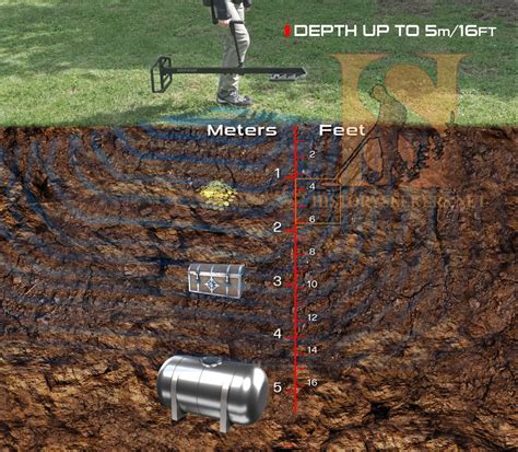
2 box metal detector circuit A simple metal detector circuit diagram and schematic using a single transistor and a radio. This metal detector/sensor project is easy to make and is an application of Colpitts oscillator. Your Source For Corrugated Sheet Metal: We ship anywhere in the US and worldwide. Our extensive supply of pre-fabricated corrugated panels provides a fast solution to most jobs.
0 · xp xtreme hunter
1 · xp extreme hunter
2 · two box metal detectors
3 · gemini 3 metal detector
4 · fisher gemini metal detector
5 · fisher gemini 3
6 · deepest seeking coin metal detector
7 · deeper metal detector
Since 1958, Forster Tool has specialized in providing precision CNC Swiss Lathe parts for a variety of industries. These include the Aerospace, Medical and Automotive industries. Our experienced machinists will provide cost effective CNC .
Our first electronic metal detector circuit, see Fig. 2, uses a Hall Effect sensor to detect weak permanent magnetic fields. Almost all ferrous objects retain some degree of magnetism, and .
A simple metal detector circuit diagram and schematic using a single transistor and a radio. This metal detector/sensor project is easy to make and is an application of Colpitts oscillator.Transmitter/Receiver Detector Our last detector circuit is suitable for locating large metal objects at greater depths—feet instead of inches. This two-box detector has been around for about 75 . This article describes a very basic BFO detector which uses only two transistors and an LM389 audio amplifier. The LM389, in fact, contains the two transistors that form the . In this article, Dev presents two versions of metal detector circuitry. First, he updates the traditional beat frequency oscillator approach, to use a digital mixer. Second, he builds one more suitable for a child, using a PIC16 .
How these two concepts are used together for a metal detector circuit, is explained in working section of this project. The figure shows the circuit diagram of metal detector. The 555 IC timer here acts as a square wave .
xp xtreme hunter
xp extreme hunter
NE555 is a precision timing circuit capable of producing accurate time delays or oscillation. A NE555 has three basic modes of operations. In the time delay or mono-stable mode of operation, the timed interval is controlled .In this project, we show how you can build a metal detector circuit with a proximity detector IC and a few basic parts.Our first electronic metal detector circuit, see Fig. 2, uses a Hall Effect sensor to detect weak permanent magnetic fields. Almost all ferrous objects retain some degree of magnetism, and those that do are easily detected with our Hall Effect ferrous-detector circuit. In this post I have explained 9 simple metal detector circuits using LC tuned concept, magnetic absorption concept, and the beat frequency oscillator (BFO) concept. The BFO technique is considered to be the most accurate and reliable methods of detecting metals.
Learn how to build a metal detector using a Colpitts oscillator and an Arduino. How Do Metal Detectors Work? In the above circuit, the series capacitor and inductor form a tank circuit. In a tank circuit, energy is transferred repeatedly between a capacitor and an inductor, resulting in oscillation. A simple metal detector circuit diagram and schematic using a single transistor and a radio. This metal detector/sensor project is easy to make and is an application of Colpitts oscillator.Transmitter/Receiver Detector Our last detector circuit is suitable for locating large metal objects at greater depths—feet instead of inches. This two-box detector has been around for about 75 years and is still one of the most popular deep-searching detectors. The basic system is shown in Fig. 6. Two non-metallic boxes serve as the

This article describes a very basic BFO detector which uses only two transistors and an LM389 audio amplifier. The LM389, in fact, contains the two transistors that form the search and reference oscillators so the whole circuit is comprised of a single IC and a handful of discrete linear components. In this article, Dev presents two versions of metal detector circuitry. First, he updates the traditional beat frequency oscillator approach, to use a digital mixer. Second, he builds one more suitable for a child, using a PIC16 microcontroller that allows push-button zeroing and adjustable sensitivity.
two box metal detectors
How these two concepts are used together for a metal detector circuit, is explained in working section of this project. The figure shows the circuit diagram of metal detector. The 555 IC timer here acts as a square wave generator and . NE555 is a precision timing circuit capable of producing accurate time delays or oscillation. A NE555 has three basic modes of operations. In the time delay or mono-stable mode of operation, the timed interval is controlled by a single external resistor and capacitor network.
In this project, we show how you can build a metal detector circuit with a proximity detector IC and a few basic parts.Our first electronic metal detector circuit, see Fig. 2, uses a Hall Effect sensor to detect weak permanent magnetic fields. Almost all ferrous objects retain some degree of magnetism, and those that do are easily detected with our Hall Effect ferrous-detector circuit. In this post I have explained 9 simple metal detector circuits using LC tuned concept, magnetic absorption concept, and the beat frequency oscillator (BFO) concept. The BFO technique is considered to be the most accurate and reliable methods of detecting metals. Learn how to build a metal detector using a Colpitts oscillator and an Arduino. How Do Metal Detectors Work? In the above circuit, the series capacitor and inductor form a tank circuit. In a tank circuit, energy is transferred repeatedly between a capacitor and an inductor, resulting in oscillation.
cnc milling machining parts pricelist
A simple metal detector circuit diagram and schematic using a single transistor and a radio. This metal detector/sensor project is easy to make and is an application of Colpitts oscillator.Transmitter/Receiver Detector Our last detector circuit is suitable for locating large metal objects at greater depths—feet instead of inches. This two-box detector has been around for about 75 years and is still one of the most popular deep-searching detectors. The basic system is shown in Fig. 6. Two non-metallic boxes serve as the This article describes a very basic BFO detector which uses only two transistors and an LM389 audio amplifier. The LM389, in fact, contains the two transistors that form the search and reference oscillators so the whole circuit is comprised of a single IC and a handful of discrete linear components. In this article, Dev presents two versions of metal detector circuitry. First, he updates the traditional beat frequency oscillator approach, to use a digital mixer. Second, he builds one more suitable for a child, using a PIC16 microcontroller that allows push-button zeroing and adjustable sensitivity.
How these two concepts are used together for a metal detector circuit, is explained in working section of this project. The figure shows the circuit diagram of metal detector. The 555 IC timer here acts as a square wave generator and . NE555 is a precision timing circuit capable of producing accurate time delays or oscillation. A NE555 has three basic modes of operations. In the time delay or mono-stable mode of operation, the timed interval is controlled by a single external resistor and capacitor network.

gemini 3 metal detector
Looking for affordable CNC machining parts? Check out Huayi International's pricelist for high-quality and cost-effective options. Contact us today!
2 box metal detector circuit|xp extreme hunter